CIS307: Layers
Physical Layer
At the physical layer we are concerned at the electrical and mechanical level
with the transmission of individual bits/characters.
We have talked of two encodings
of binary data into binary signals, Non-Return-To-Zero-Level and Differential
Manchester, that
are relevant to this topic. We have talked briefly also of
RS-232C and Ethernet.
A significant physical layer protocol is SONET (Synchronous Optical NETwork),
with a variation
called SDH (Synchronous Digital Hierarchy). It uses a binary signal
(baseband) multiplexed using
Time-Division Multiplexing. It was originally designed for the transfer of
voice data (a voice data channel is given 4Khz, thus by Nyquist Sampling
theorem, it needs 8000 samples; each sample is measured using 256 levels -
hence a voice channel requires 8000*8 bits per second = 64Kbps).
SONET multiplexes a number of voice channels, in fact it sends a
810 byte frame each 125
microseconds. Of these 810 bytes only 783 bytes carry data, the rest
is control information.
Thus the total data rate is 810 * 8 * 8000 bits/s, or 52Mbps. SONET also
comes with data rates
that are multiples of this value.
T1 is a carrier related to SONET.
It again uses multiples of the voice channel. Now every 125
microseconds we send a frame of 24 voice channels plus one framing bit.
Thus the data rate is
24*8 + 1 bits each 125 microseconds (125 microseconds = 1second/8000),
for a total of 1.544 Mbps. Other carriers use multiples of T1:
T2 is 4 times T1 plus control bits, for a total data rate of 6.312Mbps; T3 is 6 times
T2 plus extra
control bits, for a total data rate of 44.736Mbps; T4 is a combination
of 7 T3s for a total with control bits
of 274.176Mbps. T1 can be multiplexed on T2, or T3, or T4. T1, T2,
T3 can be multiplexed on SONET.
You may have heard of people/companies leasing T1 lines, or T3 lines,
or .. (rental is thousands of
dollars per month).
Data Link Layer
The data link layer transfers information reliably over the physical layer
between neighboring nodes. The connection between neighbors can be
point-to-point, i.e. a direct link, or shared, i.e. a link that is shared between a
number of nodes, as we saw with Ethernet. In the case of shared medium
we need a MAC (Medium Access Control) protocol to regulate access
to the shared medium, like CSMA/CD we saw with Ethernet. Once access is
resolved (or it is unnecessary as in point-to-point), one has DLC
(Data Link Control) which carries out the main functionality of the Data
Link Layer.
A basic problem at the data link layer
is what to do when errors are detected at the receiver end
(we have already seen how detection is done). The transmitter has to
retransmit the frame, and the question is how does the transmitter find
out that it has to do so. There is need of an ARQ (Automatic Repeat
Request) method. Three such methods are in common use:
- Stop-and-Wait: a transmitter after sending a frame waits for
a message (ACK/NACK) back from receiver indicating if the previous frame was
or not received correctly. If not, the frame is retransmitted.
- Go-Back_N: Now frames are numbered and the transmitter is allowed to
send a number of frames (up to N) without waiting for acknowledgement (see
Sliding Window Protocol below), but when the receiver sends a "NACK i"
to indicate an error with frame i, then frame i and all its transmitted
successors are retransmitted.
- Selective-Repeat: Similar to Go-Back-N, but now for
the response "NACK i" only
frame i is retransmitted.
In the case of stop-and-wait we have a problem: a sender sends a frame.
It is received and acknowledged. The ack is lost. The sender times out while
waiting for reply. Then it sends message again. At this point the receiver
has no way of knowing that this is the old frame and not a new one.
Solution: tag each frame with a sequence bit, that is 0, 1, 0, 1, ..
in successive distinct frames. But it remains at the current value
when a frame is resent. So we have;
SENDER:                                RECEIVER:
  int sequencebit = 0;                   int sequencebit = 0;
  frame oldframe (read it), newframe;    frame theframe;
  for (;;) {                             for (;;) {
    copy sequencebit to oldframe;          waitforframe(theframe, timeout);
    send oldframe;                         if (!timeout && sequencebit != bit in frame){
    waitforack(timeout);                     save theframe;
    if (!timeout && !NACK){                  sequencebit = (sequencebit+1)%2;
       read newframe;                      }
       oldframe = newframe;              }
       sequencebit = (sequencebit+1)%2;
    }
  }
Notice than in the case of both Go-Back-N and of Selective-Repeat we need
a way to identify frames. To this end one uses identifiers, say n bits,
that identify a frame among the outstanding frames. So if it uses 3 bits,
we have as identifiers 0,1,2,3,4,5,6,7 and when an id has been acknowledged
it can be reused (see sliding window protocol).
Performance of ARQ Techniques
We can express the time required to transmit a frame using Stop-and-Wait ARQ
in terms of two basic times: the Transmission Time Tt and the
Propagation Time Tp. The former is easily computed by dividing
the size of the frame by the data rate of the channel. So a 1500 Bytes frame
in Ethernet will take 1.2 ms (1,500B = 12,000b, data rate = 10Mbps).
The latter is easily computed by dividing the distance between sender and
receiver by the propagation speed of the signal (usually 200,000Km/s).
So the propagation time in Ethernet at the distance of 200 meters will be
1 microsecond.
In Stop-and-Wait the delivery time of a frame, Td, is thus (assuming that
the time to transmit an ACK or NACK is negligible and
assuming that the time to process the ACK or NACK at the receiver
is also negligible)Td = Tt +
2*Tp. This says that the utilization of the communication channel is
       Tt          1                 Tp   propagationTime
    --------- = --------  where a = --- = ----------------- =
    Tt + 2*Tp    1 + 2*a             Tt   transmissionTime
                                    propagationTime * dataRate
                                  = -------------------------- =
                                           frameSize
                                    sizeofDataInTransit
                                  = -------------------
                                        frameSize
So the utilization in our example in Ethernet is almost 100%.
But suppose we use a T1 line (1.5Mbps) to transmit a 100 Byte frame
to Los Angeles from Philadelphia (5000 kilometers), we get Tp = 25ms,
Tt = 0.5ms for a utilization of about 1%.
Things become even worse if we take into consideration the probability of
errors. Say that the probability of loss of the frame is P (we assume the
ACK/NACK never fails), then the utilization becomes
      (1 - P)
     ---------
      1 + 2*a
[this result is obtained reasoning as when we computed the round robin time
in the notes on performance evaluation.]
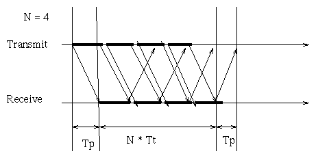
If we consider instead the Go-Back-N ARQ or the Selective-Reject ARQ
the transmission of ACKs is
overlapped with the transmission of the frames. Thus the utilization,
without worrying about errors, becomes
                            N
                      /  -------  if  N < 1 + 2*a
                      |  1 + 2*a
      utilization =   |
                      |
                      \  1        otherwise
This can be understood with the following observations:
- When N*Tt is less than (Tt + 2*Tp) the acknowledgement of the first frame
is not yet received by the transmitter when the transmitter terminates sending
all the N frames. Thus the transmitter has to
wait before sending more frames and the utilization is less than 1.
- When instead N*Tt is greater or equal than (Tt + 2*Tp) the acknowledgement for
the first frame has been received before all the frames are sent,
thus the transmitter can keep on transmitting
without idle time.
The relationship between Tp, Tt, and N is captured by the following
timeline diagram:
Sliding Window Protocol
The performance of the various ARQ techniques
shows that allowing the transmission of more than one frame
before requiring acknowledgement improves performance. In fact utilisation
increases with N. On the other hand the larger is N the larger are the
memory requirements on the sender (Go-back-N) or on both the sender and the receiver
(Selective-Reject). Thus N must be limited (this is a form of
Flow Control). The Sliding Window Protocol embodies these ideas.
It operates as follows:
- One selects the number of bits m to be used for the frame identifier.
Say m, for example 3.
- Set N to 2**m - 1. So if m is 3 N is 7 and the frames will have ids
0,1,2,3,4,5,6,7.
- The receiver will send ACK_i when it has received all the frames up
to frame i-1 included. If the receiver were to send a message to
the sender (because they have a two way conversation) it will insert
in the message the ACK_i as confirmation.
This second form of acknowledgement is said to be
piggybacked on the message from receiver to sender.
- In the sliding window protocol we cannot have 2**m outstanding frames (i.e.
frames that have been sent but not yet acknowledged).
It has been shown that:
- If the receiver accepts frames sequentially, 2**m - 1 frames can be outstanding
- If the receiver accepts frames also if they arrive out of order, then
only half of the available frames can be outstanding at any
one time (i.e. 2**(m-1)).
The argument for the sequential case is easy: if 2**m frames could be
outstanding, the receiver would never recognise that, say, frame 1 is
duplicated in the following situation: sender sends frame 0,1,..,2**m-1
then waits because it has consumed the available window; the receiver
acknowledges packet 0 and the ack gets lost; the sender who has
not received an ack for 0 after a while sends it again. Now the receiver
thinks that it is a new packet since it had already acknowledged 0.
For the non sequential case, assume that the sender sent 0, 1, .., 2**(m-1) and
the receiver acknowledges all of them by sending the ack for 2**(m-1).
Assume this ack is lost. Then when the sender resends the original frames
the receives will consider them to be old because it is expecting now
2**(m-1),2**(m-1)+1,..2**m-1.
The sliding window protocol can be generalized to the case where
the frames are of variable size and we have a bound on the cumulative size
of the frames that are outstanding.
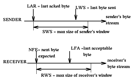
If SWS is the maximum size of the sender's window, LWS is the id of the last
frame sent, and LAR is the id of the last acknowledgement received, then
LWS - LAR <= SWS
and the sender can still send
SWS - LWS + LAR frames.
If RWS is the maximum size of the receiver's window, LFA is the id of the
last acceptable frame, NFE is the id of the next frame expected, then
LFA - NFE + 1 <= RWS
Frames with id greater than LFA or smaller that NFE are discarded by the
receiver. Usually SWS and RWS are set to be equal.
We can determine the "ideal" size in bits W of the window used in the
Sliding Window Protocol on the basis of the fact that we want to keep
on transmitting at least
until acknowledgement has been received for the initial
packet. The round trip for the acknowledgement is Tt+2Tp. If r is the data rate
at which the transmitter is transmitting, then the number of bits that can be
transmitted during the round trip is
W = r*RTT = r*(Tt+2Tp) where RTT is the Round Trip Time
The Sliding Window Protocol, in some form, is used both in the
Data Link Layer and in the Transport Layer in TCP as a form of flow control.
HDLC
HDLC (High-Level Data Link Control) is one of a family of similar data link protocols
that use the sliding window technique.
It is bit oriented with a flag sequence (it uses bit stuffing)
to indicate the start and termination of a frame.
A Frame has the form:
        8 bits    8 bits    8 bits    >=0    16 bits     8 bits
    +----------+---------+---------+------+----------+----------+
    | 01111110 | address | control | data | checksum | 01111110 |
    +----------+---------+---------+------+----------+----------+
where the address field is likely not to be used in most cases you will encounter
and the control field comes in three formats:
bits  1      3         1     3
    +---+----------+-----+-------+
    | 0 | sequence | P/F |  next |     Format for Information Frames
    +---+----------+-----+-------+

bits  1   1    2      1      3
    +---+---+------+-----+-------+
    | 1 | 0 | type | P/F |  next |    Format for Supervisory Frames
    +---+---+------+-----+-------+

bits  1   1   1     1     1       3
    +---+---+---+------+-----+----------+
    | 1 | 1 | 0 | type | P/F | modifier |  Format for unnumbered frames
    +---+---+---+------+-----+----------+
sequence specifies the sequential id of this frame in accordance to the sliding window protocol.
next is the piggibacked acknowledgement for a received frame.
type is the code for a command such as RECEIVE READY, REJECT, RECEIVE NOT READY, SELECTIVE REJECT, DISCONNECT, FRAMEREJECT.
P/F means Poll/Final and it is normally used in communication with terminals in a multidrop line.
Information frames are used to transport data. Supervisory frames are
used to transport acknowledgements and commands. Unnumbered frames
are used both for command purposes and for data transport.
PPP
PPP (Point-to-Point Protocol) is a point-to-point data link protocol related to HTLC.
It is used for example by people at home to connect through modem
to their ISP (Information Service Provider) and interact as a regular workstation directly
connected to the internet.
ARP: Address Resolution Protocol
ARP packets are broadcast to a local area netweork when we need to determine
the hardware address corresponding to a given IP address. The host with
that IP address will respond giving its own physical address.
The ARP packet used on ethernet has form:
    0                   1                   2                   3
    0 1 2 3 4 5 6 7 8 9 0 1 2 3 4 5 6 7 8 9 0 1 2 3 4 5 6 7 8 9 0 1
   +-+-+-+-+-+-+-+-+-+-+-+-+-+-+-+-+-+-+-+-+-+-+-+-+-+-+-+-+-+-+-+-+
   |    Hardware Address Type      |    Protocol Address Type      |
   +-+-+-+-+-+-+-+-+-+-+-+-+-+-+-+-+-+-+-+-+-+-+-+-+-+-+-+-+-+-+-+-+
   | HADDR length  | PADDR length  |          Operation            |
   +-+-+-+-+-+-+-+-+-+-+-+-+-+-+-+-+-+-+-+-+-+-+-+-+-+-+-+-+-+-+-+-+
   |                Sender HADDR (first 4 octets)                  |
   +-+-+-+-+-+-+-+-+-+-+-+-+-+-+-+-+-+-+-+-+-+-+-+-+-+-+-+-+-+-+-+-+
   |Sender HADDR (last 2 octets)   | Sender PADDR (first 2 octets) |
   +-+-+-+-+-+-+-+-+-+-+-+-+-+-+-+-+-+-+-+-+-+-+-+-+-+-+-+-+-+-+-+-+
   |Sender PADDR (last 2 octets)   | Target HADDR (first 2 octets) |
   +-+-+-+-+-+-+-+-+-+-+-+-+-+-+-+-+-+-+-+-+-+-+-+-+-+-+-+-+-+-+-+-+
   |                   Target HADDR (last 4 octets)                |
   +-+-+-+-+-+-+-+-+-+-+-+-+-+-+-+-+-+-+-+-+-+-+-+-+-+-+-+-+-+-+-+-+
   |                   Target PADDR (last 4 octets)                |
   +-+-+-+-+-+-+-+-+-+-+-+-+-+-+-+-+-+-+-+-+-+-+-+-+-+-+-+-+-+-+-+-+
To avoid the transmission of too many ARP packets a cache is used to keep
track of known pairs [IP address, Physical addres]. When an ARP packet
is received, its sender's pair is added to the cache if not already there.
Cache entries are eliminated either because of overflow or because
of aging of the pairs.
RARP (Reverse ARP) is used when a diskless station is booted on a LAN.
It sends out a packet with its own physical address and asks others to tell
him what is its IP address.
Network Layer
IP Role
IP provides an unreliable, best-effort, connectionless packet delivery
service between computer systems. It supports:
- Addressing: how to identify networks and hosts
- Fragmentation: it takes care of the fact that different networks
may have different MTUs (Maximum Transfer Units), and thus they may need
to fragment an existing packet when going through a network with smaller MTU.
IP does not do directly:
- Computation of Routing Tables(done by other protocols)
- Congestion control
- Flow control
- Error control
- Resource management
IP Header
    0                   1                   2                   3
    0 1 2 3 4 5 6 7 8 9 0 1 2 3 4 5 6 7 8 9 0 1 2 3 4 5 6 7 8 9 0 1
   +-+-+-+-+-+-+-+-+-+-+-+-+-+-+-+-+-+-+-+-+-+-+-+-+-+-+-+-+-+-+-+-+
   |Version|  IHL  |Type of Service|          Total Length         |
   +-+-+-+-+-+-+-+-+-+-+-+-+-+-+-+-+-+-+-+-+-+-+-+-+-+-+-+-+-+-+-+-+
   |         Identification        |Flags|      Fragment Offset    |
   +-+-+-+-+-+-+-+-+-+-+-+-+-+-+-+-+-+-+-+-+-+-+-+-+-+-+-+-+-+-+-+-+
   |  Time to Live |    Protocol   |         Header Checksum       |
   +-+-+-+-+-+-+-+-+-+-+-+-+-+-+-+-+-+-+-+-+-+-+-+-+-+-+-+-+-+-+-+-+
   |                       Source Address                          |
   +-+-+-+-+-+-+-+-+-+-+-+-+-+-+-+-+-+-+-+-+-+-+-+-+-+-+-+-+-+-+-+-+
   |                    Destination Address                        |
   +-+-+-+-+-+-+-+-+-+-+-+-+-+-+-+-+-+-+-+-+-+-+-+-+-+-+-+-+-+-+-+-+
   |                    Options                    |    Padding    |
   +-+-+-+-+-+-+-+-+-+-+-+-+-+-+-+-+-+-+-+-+-+-+-+-+-+-+-+-+-+-+-+-+

Version: Current IP  4
         Next Generation:  6 ==> IPv6 or IPng
IHL: Header Length in words:  without options it is 5, with
         options it can be as high as 15.
Type of Service: the sender specifies the type of service desired.
	 Three bits can be used to specify the priority of the message.
	 Three bits can be used to characterize the aim, if one
         that maximizes reliability, or one that minimizes delivery
         time, or one that maximizes throughput.
Total Length: 16 bits ==> maximum packet size 65,535 Bytes (64 KB)
         including header length
Identification: unique for each IP datagram
       (1) source increments a counter
       (2) gateway copies
       All the fragments of the same packet have the same identification.
Flag: three bits, two lower bits used for fragmentation, the third is not used:
       (1) first bit if 1, means do not fragment (this is the DF flag)
       (2) second bit if 1, means more fragment are coming (not end of packet)
          (This is the MF flag.)
Fragment Offset: offset in the original datagram in units of 8 octets. All
       fragments, except the last, must me multiples of 8 octets.
TTL:   each gateway decrements TTL by some number and discard the packet if it
       reaches 0. If discarded, the sender is informed using the ICMP (Internet
       Control Message Protocol) protocol.
       In theory, it counts in second units and discards a packet that takes
       255 seconds to propagate.
Protocol: number of the higher level protocol that is using the current packet
       ICMP: 1, TCP: 6, UDP: 17
checksum: it is the one-complement of the one-complement sum of the header.
       Notice that it is the one-complement so that at the receiver no
       subtraction is required, just a comparison to zero.
Some observations on IP protocol:
- Fragments of a packet are not re-assembled together until the final
destination is reached. There, if a fragment is missing, or a fragment
is with bad data check, all the fragments are discarded.
- If necessary, a fragment may be further decomposed. All the fragments of a
packet have the same header, except for minor differences like fragment offset,
flags, checksum.
- When an IP packet arrives at a router its header checksum is computed
and, if incorrect, the packet is discarded.
ICMP: Internet Control Message Protocol
It is encapsulated within an IP packet.
It supports the following message types:
- Source Quench: A router that has to discard a packet because it has run
out of buffer space sends a Source Quench message to the source of the packet.
That source will have to slow down the rate at which it sends packets.
- Time Exceeded: It is sent to the source of a packet when a router has to
discard that packet since its TTL has reached zero, or when the destination
of the packet is unable to collect all the fragments of the packet before the
time out expires.
- Destination Unreacheable: sent to source of packet when a router cannot find
its destination, either network or host.
- Fragmentation Required: when there is need of fragmentation, but fragmentation
is not allowed because the non fragmentation flag is set in the packet.
- Echo Request/Reply: When a node receives an Echo Request it is supposed to send a
Echo Reply message.
- Address Mask Request/Reply: When a host first starts, it sends an
Address Mask Request on the local network and a local router replies
with an Address Mask Reply indicating the subnet mask of the network.
- Redirect: Used by a router to say to sender the id of another
router better suited for sending messages to specified receiver.
ICMP is used to implement ping (using the EchoRequest/Reply
messages), traceroute (IP using the TimeToLive, and ICMP using the
TimeExceeded message), and to determine a
path's MTU (IP using the DF flag and ICMP using the FragmentationRequired
message). It is also used to report on errors that occur during the
transmission of IP packets.
Transport Layer
It supports communication between processes (not just computer systems).
UDP Header
The User Datagram Protocol is the simplest transport protocol.
It just adds multiplexing, in the form of ports, unsigned 16 bit
integers, to the IP protocol, and a simple error check, in the form
of a checksum. The checksum is computed over the UDP datagram
(UDP header + message) plus
three fields from the enclosing IP packet:
length+SourceAddress+DestinationAddress.
The reason for using these three extra fields is the desire to detect
if in transit the source or destination of the packet have been modified
[this is not to detect a malicious router, but to detect a routing
mistake]. The checksum is computed as in the case of IP packets (one
complement of one-complement sum).
The messages exchanged are called datagrams,
i.e. communication is connectionless. The format of the UDP header is:
    0                   1                   2                   3
    0 1 2 3 4 5 6 7 8 9 0 1 2 3 4 5 6 7 8 9 0 1 2 3 4 5 6 7 8 9 0 1
   +-+-+-+-+-+-+-+-+-+-+-+-+-+-+-+-+-+-+-+-+-+-+-+-+-+-+-+-+-+-+-+-+
   |          source port          |        destination port       |
   +-+-+-+-+-+-+-+-+-+-+-+-+-+-+-+-+-+-+-+-+-+-+-+-+-+-+-+-+-+-+-+-+
   |         checksum              |          length               |
   +-+-+-+-+-+-+-+-+-+-+-+-+-+-+-+-+-+-+-+-+-+-+-+-+-+-+-+-+-+-+-+-+
TCP Header
The Transmission Control Protocol (TCP) is a connection oriented
[thus sender and receiver are as connected in a virtual circuit],
bidirectional [i.e. full duplex],
stream oriented [as opposite to message oriented,
i.e. users think in terms of sending and receiving a stream of
octets; the implementation will actually use messages, called segments.]
reliable transmission protocol at the transport layer.
The same format for the header is used in both directions in a
connection.
Here is a picture of the header of a segment and a description
of some of its fields.
    0                   1                   2                   3
    0 1 2 3 4 5 6 7 8 9 0 1 2 3 4 5 6 7 8 9 0 1 2 3 4 5 6 7 8 9 0 1
   +-+-+-+-+-+-+-+-+-+-+-+-+-+-+-+-+-+-+-+-+-+-+-+-+-+-+-+-+-+-+-+-+
   |          source port          |        destination port       |
   +-+-+-+-+-+-+-+-+-+-+-+-+-+-+-+-+-+-+-+-+-+-+-+-+-+-+-+-+-+-+-+-+
   |                        sequence number                        |
   +-+-+-+-+-+-+-+-+-+-+-+-+-+-+-+-+-+-+-+-+-+-+-+-+-+-+-+-+-+-+-+-+
   |                 acknowledgement number                        |
   +-+-+-+-+-+-+-+-+-+-+-+-+-+-+-+-+-+-+-+-+-+-+-+-+-+-+-+-+-+-+-+-+
   | TCP |             |U|A|P|R|S|F|                               |
   |Headr|             |R|C|S|S|Y|I|       window size             |
   |lengt|             |G|K|H|T|N|N|                               |
   +-+-+-+-+-+-+-+-+-+-+-+-+-+-+-+-+-+-+-+-+-+-+-+-+-+-+-+-+-+-+-+-+
   |       checksum                |   urgent pointer              |
   +-+-+-+-+-+-+-+-+-+-+-+-+-+-+-+-+-+-+-+-+-+-+-+-+-+-+-+-+-+-+-+-+
   |                    Options (0 or more words)                  |
   +-+-+-+-+-+-+-+-+-+-+-+-+-+-+-+-+-+-+-+-+-+-+-+-+-+-+-+-+-+-+-+-+
- Source and Destination Ports:
- They are 16 bit numbers. A port number is local to a specific
host, i.e. different hosts have
65,535 different ports.
In unix /etc/services keeps a list of
specific uses for some of these ports.
For example, HTTP uses 80, Telnet
uses 23, FTP uses 21. The first 1024 ports are said to be "well known" and
are reserved.
Notice that ports allow us to communicate
with specific programs on a computer, not just with a computer as in IP.
- Sequence and Acknowledgement Numbers:
- These numbers are local to a connection between two nodes,
they are unique during the life of message. The initial sequence number
is agreed between the sender and the receiver when the connection is set up
with a Three-Way-Handshake [SYN->, SYN+ACK<-, ACK->].
For example, if two nodes A, B are communicating, then A as sender
may choose initially the number 200 and
B as sender may choose initially the number 500.
Then B will acknowledge messages relative to 200 and A will acknowledge
messages relative to 500.
- Length of the TCP header:
- It is counted in 32-bit words.
- Flags:
- There are six flags:
- URG: It is 1 if the Urgent Pointer is used.
- PUSH: Request, on sender, that this segment should be transmitted asap,
and, on the receiver, that it be delivered asap.
- ACK: Confirms that the acknowledgement field is valid
- SYN: Request to setup a connection. It must be acknowledged.
- FIN: Request to shutdown. It must be acknowledged.
- RESET: Receiver is confused. It requests the sender to abort the
connection.
- Window Size:
- It specifies the size of the receiver's available buffer (called
window).
- Urgent pointer:
- Byte offset from the current sequence number at which urgent
data will be found.
- CheckSum:
- Defined as in UDP.
Some of the issues dealt with at the transport level, in particular by
TCP, are:
- Message identification: Managing identifiers for messages to make sure
that stale messages (i.e. messages that are still in the network, but have
been superceded by other messages)
do not create confusion. It uses lower k bits from the local timer. One must
make sure that no two messages are sent for the same tick of the clock (that is usually
the case) and that no message remains alive across the intervening time (2^k ticks).
The transmitter and receiver both identify their messages and these identifiers
are usually different.
- Connection management, both starting and terminating a connection, and multiplexing
multiple connections.
A connection is started by a client (active open) using a
three-way handshake.
The transmitter sends ConnectionRequest(seq=x,SYN)
to start a connection with transmitter id x.
The receiver, the server that previously performed a passive open,
replies ConnectionAccepted(seq=y, SYN+ACK=x+1),
to acknowledge x (ready to accept x+1) and establish for its
messages the identity y. Finally the transmitter confirms the connection
with ConnectionAccepted(seq=x,ACK=y+1)
to confirm its own identifier x and accept the receiver's
identifier y (ready to accept y+1).
If the receiver wanted to reject x, it would send Reject(ACK=x), and if the
transmitter wanted to reject y it would send Reject(ACK=y).
As part of the handshake the
transmitter and receiver specify their MSS (Maximum Segment Size),
that is the maximum size of
a segment they can accept. A typical value for MSS is 1460.
A connection is terminated with a similar four-way handshake
[FIN->, ACK<-, FIN<-, ACK->]. For more information on these handshakes,
and a state diagram that helps you see what is going on, see the
notes on sockets.
- Error management, including error detection, error control, choosing
timeouts.
For timeouts, for each distinct destination one keeps track of round
trip times, RTT,
and chooses a timeout that is computed from the recent RTTs. One may compute
an estimated
RTT that is the exponential average of the RTTs and then choose the timeout as 2 times that
estimate. [Exponential averaging assumes a number a, 0<=a<=1, and computes a
sequence of estimated RTTs according to the formula
ERTT(i+1) = a*ERTT(i) + (1-a)*RTT(i).]
In the case of TCP a more sophisticated method is used.
It computes a timeout value using information
about the average and standard deviation of the round trip times, and does
so without need for floating point arithmetic (it uses approximations).
- Managing message fragmentation.
- Flow Control. Here we use the Sliding Window Protocol. Remember that flow control deals
with the ability of the end receiver of a transmission to deal with incoming messages.
- Congestion Control.
Remember that congestion control deals with the ability of the network to
deal with current traffic, i.e. it refers to the intermediate routers and
links, not to the endpoints of the transmission.
Congestion Collapse is what could happen when IMPs get overloaded,
run out of buffer space and start throwing away incoming segments. Then
the original sender times out and sends additional copies of the segments that
add to the traffic.
These are complex issues whose solutions go by interesting names slow
start, fast retransmit, and fast recovery.
The transmitter knows the receiver's window from the Sliding Window Protocol.
It maintains in addition a Congestion Window and a Threshold,
initially 64KB. The amount of data that can be transmitted is the minimum of
the sliding window and the congestion window.
The congestion window starts at the maximum size of a segment.
If a message is acknowledged, the congestion window is incremented
by one segment, and so on until
the threshold is reached or a message is lost due to congestion. When the
threshold is reached, the congestion window can still grow, but now
it is incremented
by a single maximal segment per round-trip time.
When a message is
lost, the threshold is set to 1/2 of the congestion window and the congestion
window is restarted at the size of the maximum segment. [Of course you
may wonder how the sender knows that a segment is lost - for example by
timeout, or double-acknowledgement for the start byte of the lost segment.]
Another technique for dealing for congestion: we are in the case where
small data messages are being send, say, single characters in a telnet
session. The Nagle Algorithm deals with this situation: the user
types at some speed. The first character is sent immediately. The others
are accumulated and sent together when either ACK comes back from receiver,
or 500ms have elapsed. A symmetric arrangement can be made in receiver
publicizing that the available window not when it transitions from 0 to 1 but
to a larger number (like half the buffer size).
ingargio@joda.cis.temple.edu